Wow very nice @x-jets!
Why not move the prop forward, less tork and you can get support by the mast.
So there is one thing that I see as a challenge. As the belt is going around it have to squeeze out water from between the pulleyes and the belt teeths. As we all know water is harder to move around than air. It will be very interesting to see how air/water drive is affecting the efficiency of the transmission. Maybe it would make sens to make the grooves deeper, with special channels or holes to give the squeezed water a place to go?
Looked around for examples of belt drives under water, does not seem to be very common. It will also be interesting to see how the belt keeps up with salt water, as I assume they are noe designed for this, altho I think that is a small concern in the bigger picture.
1 Like
Tooth shape could be modified as there is a lot of contact, a less efficient tooth perhaps more wave-like is made up for by quantity. The teeth are naturally open on the sides, so plenty of space for the water to squeeze, but correct, it is an unknown right now. Salt water should be no problem with rubber construction, we use it in power hoses in hydroflight all the time, no issues.
@Flex spacing right now is due to the internal stack of plug - motor - coupling - bearings - seals - toothed gear. Turning that around would mean routing the wiring through everything. Supporting off the mast seemed to be more problematic for maintaining alignment then off the same axis as the motor.
@hotwireaddict Certainly looking at the shrouding of the belt. Construction-wise it is a little tougher to mount cleanly into the tube in front of the motor, and seemed cleaner to have a rigid enough axle from the back only, we’ll see.
Squeezing out of air is one reason why cars are so loud in reverse. Reverse gears are not used very often, so car manufacturers put in straight gears instead of helical gears to save money. Helical gears can push out the air gradually from in between the teeth.
We’ll see what the results are. Tension required is higher, but flat drive belts might be an option.
1 Like
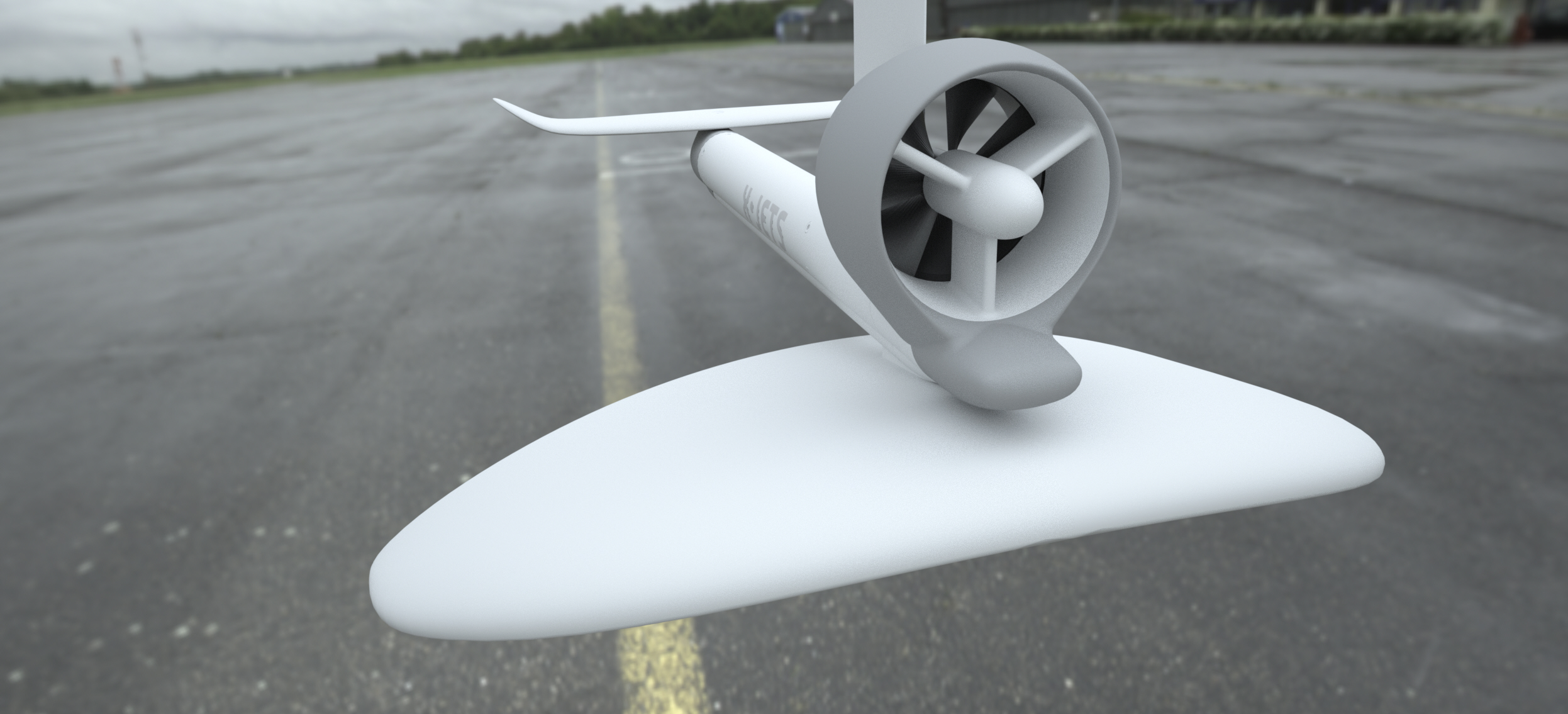
Current state of the mechanics of the belt drive (rear wing connection point not detailed). Open to show belt access.
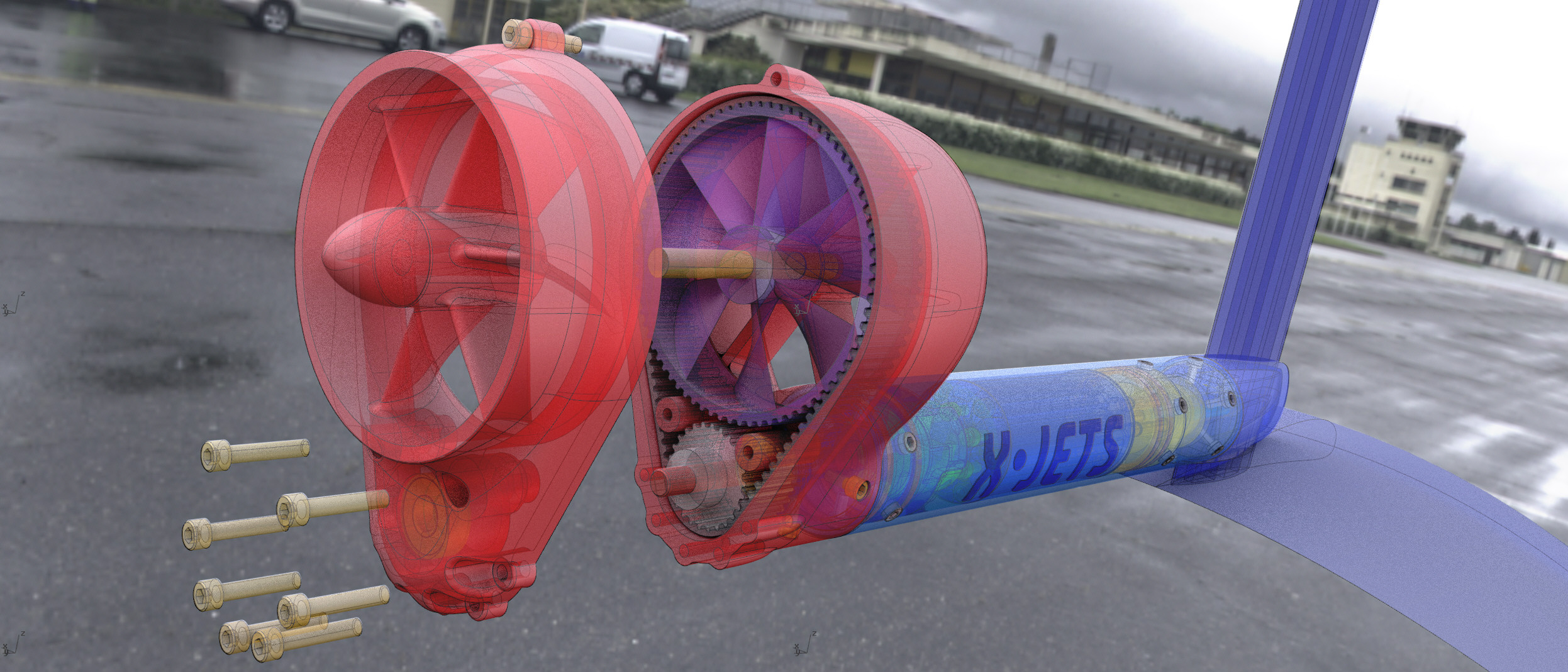
5 Likes
Looks very nice, but also difficult to manufacture unless you 3 D print the parts.
All designed with planar draft angles, actually designed for CNC, I am old school.
Like your design. Maybe it would be possible to attach the toothed pulley directly to the motor shaft to shorten the over all length of the drive. You might need a longer shaft and it will be harder to fix the propeller unit to the tube. The force on the parts linking the tube (motor) and the Propeller will be quite high I think.
Thanks! The issue there is the alignment, forces and space for sealing. I think it best to isolate the motor with a flexible coupling that can handle some of the imperfect forces due to machining tolerances and working forces. Right now the design has three bearings on the shaft, two to stablize around the seals and the third open at the outside end after the toothed pulley, three mating sections structural section traverse the shaft length. The propeller shaft should be well supported by the intake grate and stator stages. Those parts are going to be CNC alloy.
Luckily the loads acting on the shafts are easy to calculate it would be nice to know the required torque on the prop.
1 Like
I dont understand this concept, i think to much unnecessary components are elevated the resitance…
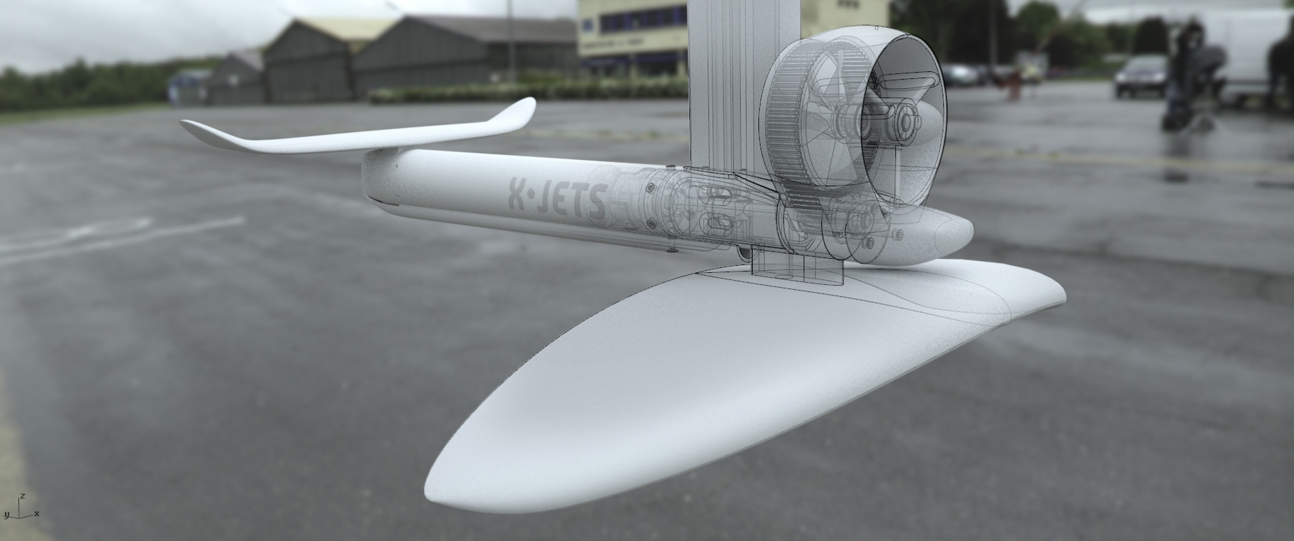
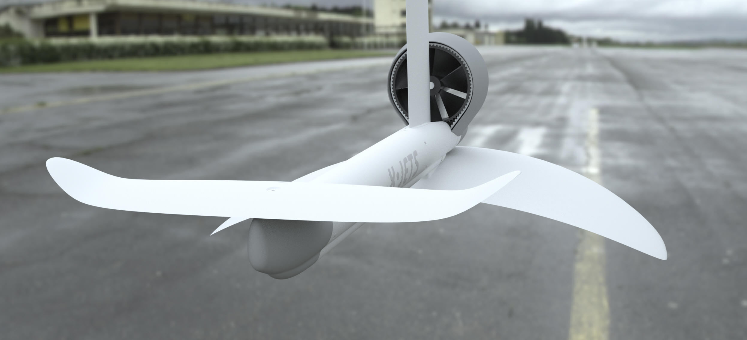
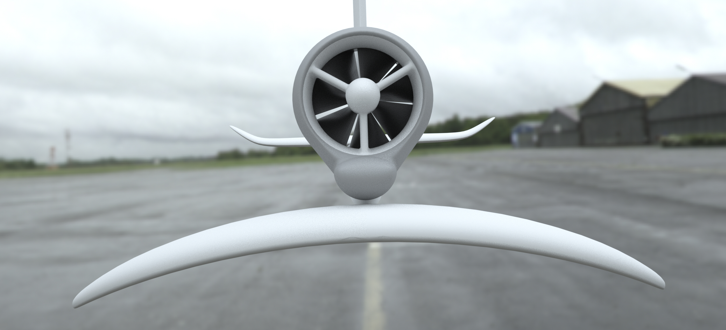
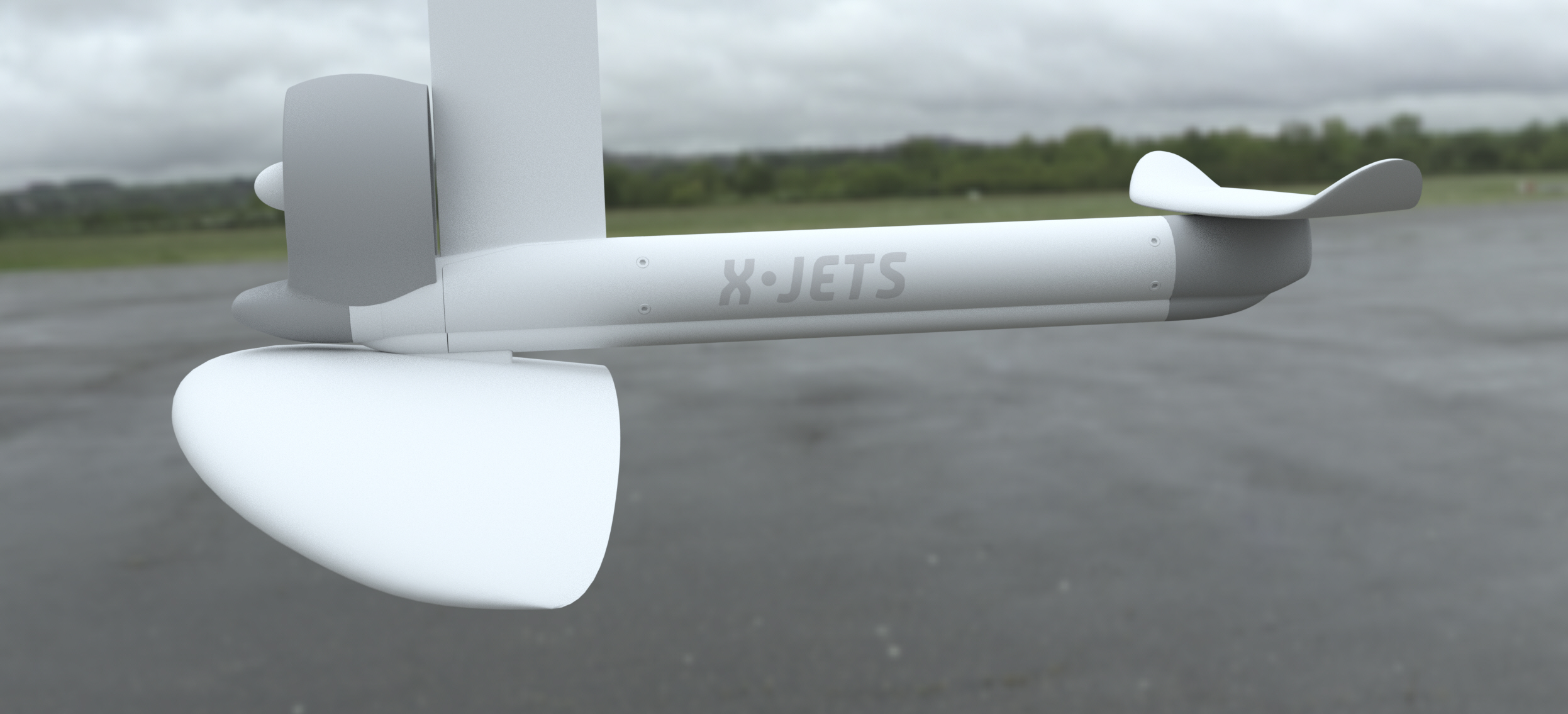
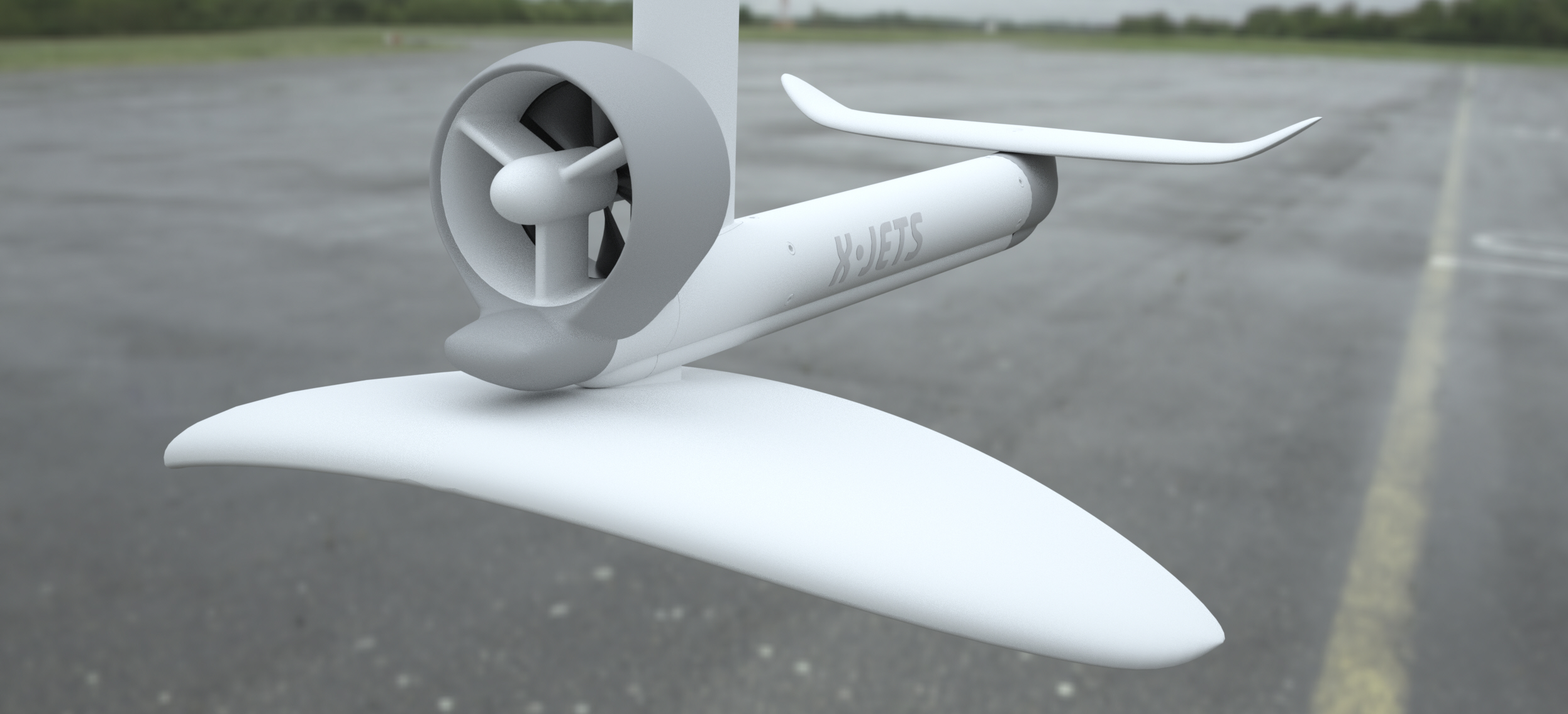
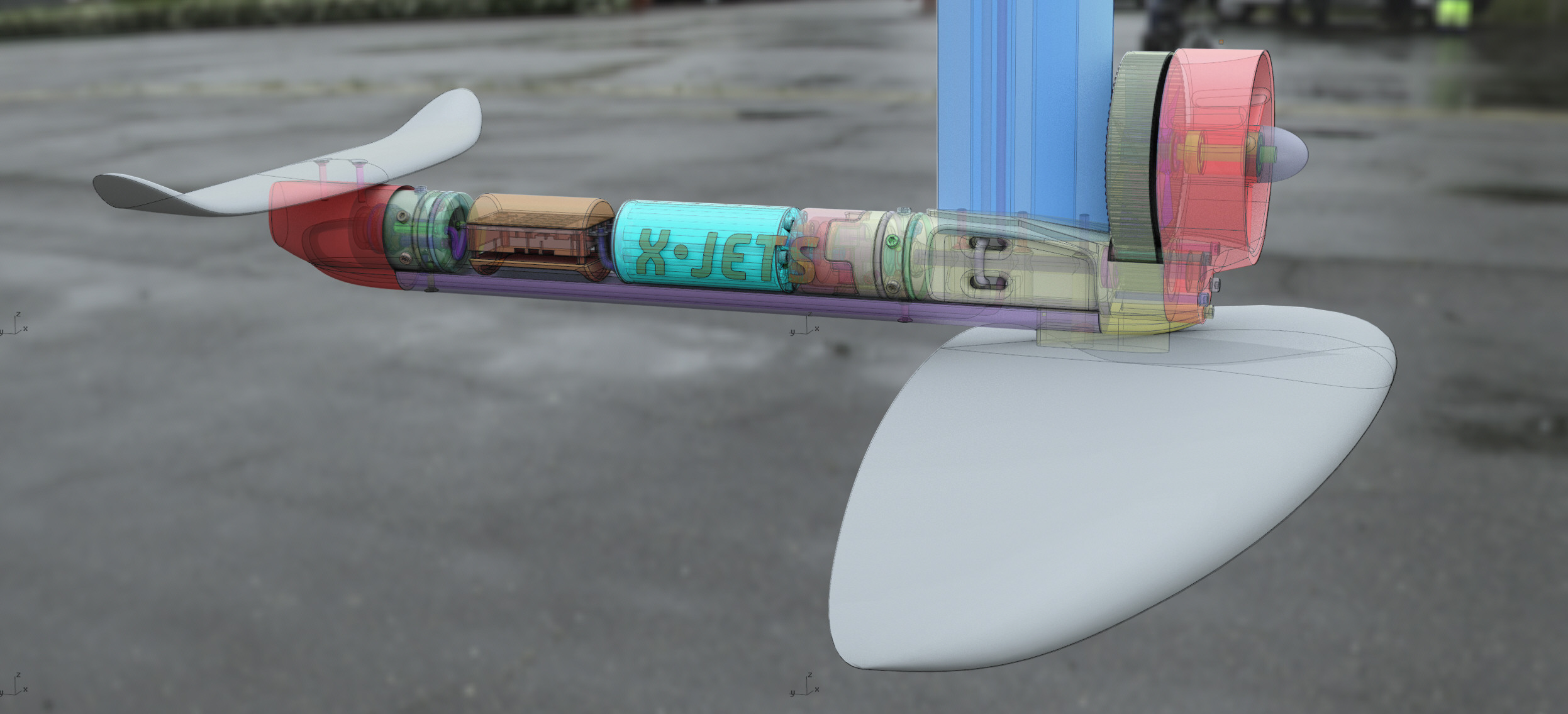
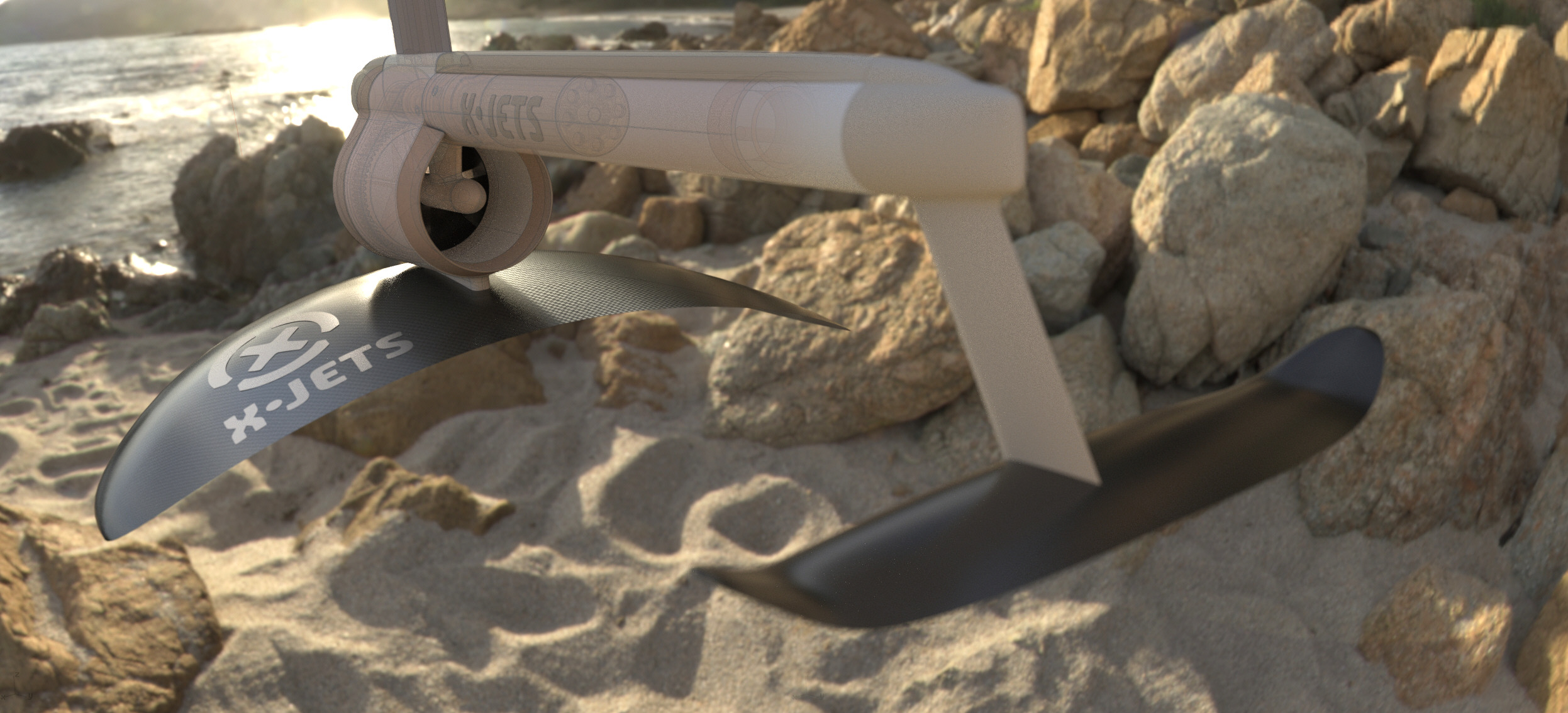
Belt reduction is now the maximum, 4:1, moving the prop to the front was a structural challenge, the solution being to route the wiring around the axle and mount the mast above the axle with that chassis linking the structures for and aft. Various solutions studied with “Scan and Solve Pro” FEA software from Intact Solutions, recommended. Additional fairing solutions to be finalized. Rear of belt can be shielded past the first proto. Thanks for all of the feedback that has helped to push forward this exploration.
6 Likes
I like how those are looking. Are you going to build any of them? I have tons of extra stuff from building eskates that I could use, so I am interested in doing a belt system in the future. I bought everything to to PMeister build this summer because I am tired of building and testing. However for the good of everyone else, a belt system would be much cheaper to implement. a good 6364 motor, belt and pulleys would be half the cost of the sss motor alone. I keep hoping someone will step up a just do a DIY package like what was done with esk8s.
My thought is that the prop pulley seems to be so much larger than what I would think necessary. Eskates use a 4 to one reduction (44 tooth and 12 tooth spur) and the pulley is no where near that large. Depends on the motor pulley size I guess. A smaller pulley would allow an even more streamlined design. I might just print out an easy design for my Slingshot foil and see how it works. Probably after I get a working board though!
Appreciate it. Yes, we are converging on the trial design, we have the initial components and have lined up the sources for most components. We’ll start cnc work after Chinese New Year based on this design. This evolution from the top of this page to the current posts reflects the incorporation of the feedback and evolution from each publication.
What is the tooth pitch of the belts in eskates? 5mm is the pitch that we arrived at here based on strength and meters per second allowable speed of the belt and sprockets. Working diameter was based around a target of roughly 100mm prop with the required thickness of teeth and supporting material. The small gear is 18 teeth, which has six full teeth engaged in the belt, which is recommended, and fits the 10mm drive axle. Going smaller seemed to be problematic, but did not look hard at smaller. The pulley fits easily into the “shadow” of the motor, and dropping the prop and surrounding sprocket closer drops it into the “shadow” as well. All of that factored into this choice. We’ll see the directions it needs to be modified.
for the first 30-sec I did not realize these where renders ha ha
Just a minor thing: I would make the propeller housing struts flush with the front bearing housing. That makes it a bit smoother and a tiny bit safer since there is a wider surface area in case you hit it with your face and your fingers need to reach deeper to touch the prop. Jellyfish or seaweed would also be better deflected.
I feel the belt is rather wide. It will cost some efficiency to squeeze out the water between belt and spur. This squeezing out in air is already a problem at high RPM and is greatest source of noise in a belt drive system. The wider the belt is, the greater the problem. There are belts which have helical toothing to face this problem.
They do not need any spur gear.
I do not want to be the spoilsport, but your design is the most complex and challenging one to get a prop turned i have ever seen. It might be possible to build it and maybe it works somehow, but the existing solutions are much easier to build, mount and maintain.